
“In rocketry, software bugs don’t throw exceptions—they create craters. If your state estimation fails at high speeds, gravity wins.”
— Debugging telemetry at 3 AM.
1. Motivation & Mission Profile
Commercial off-the-shelf (COTS) altimeters and flight computers are standard in high-power model rocketry, but they operate primarily as “black boxes.” Most rely on naive barometric pressure differentiation or fixed pyro delay timers, offering little room for custom sensor fusion, low-latency telemetry downlinks, or active control hooks (such as Thrust Vector Control).
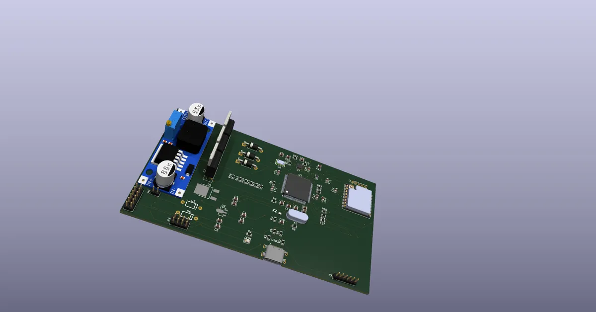
Project IGNIS is an ongoing, fully open-source aerospace development platform designed to bridge the gap between hobbyist rocketry and aerospace avionics. The core mission profile demands:
- Deterministic State Estimation: Running a high-rate physics loop (100 Hz to 250 Hz) executing an onboard Kalman Filter to accurately estimate altitude, vertical velocity, and acceleration.
- Mach Dip & Shockwave Immunity: Preventing false apogee deployment caused by aerodynamic compressibility effects and dynamic pressure spikes.
- Fail-Safe Dual Deployment: Independently driving drogue and main parachute deployment channels with hardware-level brownout isolation and continuity monitoring.
- Long-Range Real-Time Telemetry: Downlinking serialized binary telemetry packets over a robust LoRa PHY link while logging raw sensor arrays to onboard non-volatile SPI flash memory.
2. Hardware Architecture & Electrical Design
Avionics systems in rocketry experience severe physical and electrical environments: continuous motor vibration, high-G mechanical shocks, thermal dissipation constraints within sealed fiberglass airframes, and electrical noise from inductive pyrotechnic actuators.
2.1 Avionics Subsystem Breakdown
| Subsystem | Component / IC | Interface | Specifications & Role |
|---|---|---|---|
| Main Processing Unit | 32-Bit ARM Cortex-M4 / ESP32-S3 | SPI / I2C / UART | Runs the 100 Hz RTOS control loop, Kalman filter matrix math, and FSM |
| High-Precision Barometer | MS5611 / BMP280 | SPI (Up to 10 MHz) | 24-bit ADC; altitude resolution down to 10 cm for apogee tracking |
| High-G IMU | BMI088 / MPU6050 | SPI / I2C | 16-bit 6-DOF sensor; accelerometer and gyroscope |
| Telemetry Transceiver | Semtech SX1276 / SX1278 | SPI | LoRa modulation at 433/868/915 MHz; downlinks live attitude, altitude, and state |
| Blackbox Flash | Winbond W25Q128 (16 MB) | Quad-SPI / SPI | Logs raw, uncompressed 100 Hz sensor frames for post-flight reconstruction |
| Pyro Drivers | N-Channel Power MOSFETs + Optoisolators | GPIO (Logic High) | Dual channels with rating; fires nichrome e-matches |
| Power Management | TPS62160 Step-Down + LP5907 LDO | Power Rail | Dual isolated domains: ultra-low-noise logic and pyro rail |
2.2 Power Distribution & Noise Isolation
A major failure mode in custom flight computers is microcontroller brownout during pyro actuation. An electronic match (e-match) or nichrome wire acts nearly as a direct short when ignited, pulling to instantaneously.
To guarantee zero voltage dip on the digital rails:
- Physical Rail Separation: The primary power source (2S LiPo, nominal) branches immediately into two isolated paths:
- Actuator Path: Feeds directly to the pyro terminal blocks through high-current traces.
- Logic Path: Passes through a reverse-protection Schottky diode and an array of low-ESR bulk decoupling capacitors ( tantalum parallel with ceramic), feeding a high-frequency synchronous step-down buck converter.
- Galvanic & Optical Isolation: The gate of each low-side N-channel MOSFET is driven through an optocoupler (e.g., PC817 or dedicated gate driver) with pull-down resistors () ensuring pins remain strictly low during microcontroller bootup and reset cycles.
- Continuity Detection: A small sensing resistor network () passes a safe sub-milliamp current () through the e-match to an ADC pin, allowing the firmware to verify loop continuity before arming the launch pad.
3. Mathematical State Estimation: 1D Linear Kalman Filter
Relying on raw barometric pressure to compute velocity via discrete differentiation () amplifies high-frequency noise, creating wild velocity oscillations that trigger premature parachute deployments.
IGNIS integrates accelerometer readings with barometric pressure using a 1D Linear Kalman Filter (LKF).
3.1 Kinematic State Vector & Process Model
The continuous-time kinematic model of the rocket moving along its vertical axis is governed by Newton’s equations of motion:
Where represents process disturbance (jerk/noise) modeled as zero-mean white Gaussian noise with variance .
We define the discrete state vector at sample step with interval :
The discrete-time state transition matrix is:
The discrete Process Noise Covariance matrix derived from continuous white noise spectral density is:
3.2 Measurement Model
The sensor payload provides two direct observations:
- Barometric altitude:
- Inertial acceleration:
The measurement vector and observation matrix are:
The Measurement Covariance matrix incorporates sensor noise variances:
3.3 The Recursive Filter Loop
At every sample interval ( for ):
1. Prediction Step:
2. Innovation & Kalman Gain Calculation:
3. State & Covariance Update:
Because is a matrix, its inversion is computed analytically without numerical linear algebra overhead:
4. Deterministic Flight State Machine (FSM)
The flight computer software architecture uses a strict finite-state machine. State transitions require cross-validation across multiple sensor thresholds and timing lockouts.
[ PAD_IDLE ]
│
│ Launch Detect: (a_z > 25 m/s² for 100 ms) AND (Altitude > 10 m)
▼
[ BOOST ]
│
│ Motor Burnout: (a_z <= 0 m/s²) AND (Flight Time > Min Burn Time)
▼
[ COAST (Mach Lockout Active) ]
│
│ Apogee Detect: (v_z <= 0 m/s) AND (Baro Altitude Decreasing)
▼
[ APOGEE -> EJECT DROGUE ]
│
│ Drogue Descent: Terminal Velocity ≈ 25 m/s
▼
[ DROGUE_DESCENT ]
│
│ Main Altitude Threshold: (Altitude <= 150 m AGL)
▼
[ MAIN -> EJECT MAIN ]
│
│ Main Descent: Terminal Velocity ≈ 5 m/s
▼
[ MAIN_DESCENT ]
│
│ Landing Detect: (|v_z| < 0.5 m/s) AND (|a_z| < 1.5 m/s²) for 5 seconds
▼
[ LANDED (LoRa Beacon Active) ]Transition Validation Rules
PAD_IDLEBOOST: Requires sustained vertical acceleration () for consecutive sample cycles () combined with a barometric altitude gain above pad level.BOOSTCOAST: Triggered when motor thrust ceases and vertical acceleration drops below zero ().COASTAPOGEE: Filtered vertical velocity verified across consecutive cycles, provided the flight duration exceeds the motor’s minimum burnout timer.APOGEEDROGUE_DESCENT: Drogue pyro channel is energized for .DROGUE_DESCENTMAIN_DESCENT: Filtered altitude drops below the preset recovery ceiling ( AGL). Main pyro channel is energized.MAIN_DESCENTLANDED: Filtered velocity falls within and altitude variation remains within over .
5. C++ Firmware Implementation
Below is a production-grade implementation of the non-blocking state machine and analytical Kalman Filter:
#include <stdint.h>
#include <stdbool.h>
#include <math.h>
// Flight States
typedef enum {
STATE_PAD_IDLE = 0,
STATE_BOOST,
STATE_COAST,
STATE_APOGEE,
STATE_DROGUE_DESCENT,
STATE_MAIN_DESCENT,
STATE_LANDED
} FlightState_t;
// Kalman Filter Structure
typedef struct {
float x; // Altitude (m)
float v; // Velocity (m/s)
float a; // Acceleration (m/s^2)
float P[3][3];
float Q_var;
float R_baro;
float R_accel;
} KalmanFilter1D_t;
// Global Flight Data
FlightState_t current_state = STATE_PAD_IDLE;
KalmanFilter1D_t kf;
uint32_t launch_timestamp = 0;
uint32_t state_entry_time = 0;
float ground_pressure_pa = 101325.0f;
void kalman_init(KalmanFilter1D_t *filter, float q_noise, float r_baro, float r_acc) {
filter->x = 0.0f;
filter->v = 0.0f;
filter->a = 0.0f;
filter->Q_var = q_noise;
filter->R_baro = r_baro;
filter->R_accel = r_acc;
for (int i = 0; i < 3; i++) {
for (int j = 0; j < 3; j++) {
filter->P[i][j] = (i == j) ? 1.0f : 0.0f;
}
}
}
void kalman_predict_and_update(KalmanFilter1D_t *f, float z_baro, float z_acc, float dt) {
// 1. Predict State
float x_pred = f->x + f->v * dt + 0.5f * f->a * dt * dt;
float v_pred = f->v + f->a * dt;
float a_pred = f->a;
// 2. Predict Covariance (P = F * P * F^T + Q)
float dt2 = dt * dt;
float dt3 = dt2 * dt;
float dt4 = dt3 * dt;
float p00 = f->P[0][0] + dt * (f->P[1][0] + f->P[0][1]) + dt2 * (f->P[2][0] + f->P[0][2] + f->P[1][1]) + f->Q_var * (dt4 / 4.0f);
float p01 = f->P[0][1] + dt * (f->P[1][1] + f->P[0][2]) + dt2 * f->P[2][1] + f->Q_var * (dt3 / 2.0f);
float p02 = f->P[0][2] + dt * f->P[1][2] + f->Q_var * (dt2 / 2.0f);
float p11 = f->P[1][1] + dt * (f->P[2][1] + f->P[1][2]) + f->Q_var * dt2;
float p12 = f->P[1][2] + dt * f->P[2][2] + f->Q_var * dt;
float p22 = f->P[2][2] + f->Q_var;
// 3. Compute Innovation Matrix S = H * P * H^T + R
float S00 = p00 + f->R_baro;
float S01 = p02;
float S10 = p02;
float S11 = p22 + f->R_accel;
// 4. Invert 2x2 Matrix S
float det = (S00 * S11) - (S01 * S10);
if (fabsf(det) < 1e-7f) return;
float invDet = 1.0f / det;
float iS00 = S11 * invDet;
float iS01 = -S01 * invDet;
float iS10 = -S10 * invDet;
float iS11 = S00 * invDet;
// 5. Compute Kalman Gain K = P * H^T * inv(S)
float K[3][2];
K[0][0] = p00 * iS00 + p02 * iS10;
K[0][1] = p00 * iS01 + p02 * iS11;
K[1][0] = p01 * iS00 + p12 * iS10;
K[1][1] = p01 * iS01 + p12 * iS11;
K[2][0] = p02 * iS00 + p22 * iS10;
K[2][1] = p02 * iS01 + p22 * iS11;
// 6. Update State with Measurement Residuals
float y_baro = z_baro - x_pred;
float y_accel = z_acc - a_pred;
f->x = x_pred + K[0][0] * y_baro + K[0][1] * y_accel;
f->v = v_pred + K[1][0] * y_baro + K[1][1] * y_accel;
f->a = a_pred + K[2][0] * y_baro + K[2][1] * y_accel;
// 7. Update Covariance Matrix P = (I - K * H) * P
f->P[0][0] = (1.0f - K[0][0]) * p00 - K[0][1] * p02;
f->P[0][1] = (1.0f - K[0][0]) * p01 - K[0][1] * p12;
f->P[0][2] = (1.0f - K[0][0]) * p02 - K[0][1] * p22;
f->P[1][0] = -K[1][0] * p00 + p01 - K[1][1] * p02;
f->P[1][1] = -K[1][0] * p01 + p11 - K[1][1] * p12;
f->P[1][2] = -K[1][0] * p02 + p12 - K[1][1] * p22;
f->P[2][0] = -K[2][0] * p00 + (1.0f - K[2][1]) * p02;
f->P[2][1] = -K[2][0] * p01 + (1.0f - K[2][1]) * p12;
f->P[2][2] = -K[2][0] * p02 + (1.0f - K[2][1]) * p22;
}
void process_flight_fsm(float raw_accel_z, float raw_pressure_pa, uint32_t now_ms) {
float dt = 0.01f; // 100 Hz fixed loop
float raw_altitude = 44330.0f * (1.0f - powf(raw_pressure_pa / ground_pressure_pa, 0.190295f));
float net_accel = raw_accel_z - 9.80665f;
kalman_predict_and_update(&kf, raw_altitude, net_accel, dt);
switch (current_state) {
case STATE_PAD_IDLE:
if (kf.a > 24.5f && kf.x > 8.0f) {
current_state = STATE_BOOST;
launch_timestamp = now_ms;
}
break;
case STATE_BOOST:
if (kf.a <= 0.0f && (now_ms - launch_timestamp) > 500) {
current_state = STATE_COAST;
}
break;
case STATE_COAST:
// Apogee Condition: Zero vertical velocity crossing
if (kf.v <= 0.0f && (now_ms - launch_timestamp) > 1500) {
fire_pyro_channel(0); // Fire Drogue
current_state = STATE_DROGUE_DESCENT;
state_entry_time = now_ms;
}
break;
case STATE_DROGUE_DESCENT:
if (kf.x <= 150.0f && (now_ms - state_entry_time) > 2000) {
fire_pyro_channel(1); // Fire Main
current_state = STATE_MAIN_DESCENT;
}
break;
case STATE_MAIN_DESCENT:
if (fabsf(kf.v) < 0.4f && (now_ms - launch_timestamp) > 10000) {
current_state = STATE_LANDED;
}
break;
case STATE_LANDED:
enable_locator_beacon();
break;
default:
break;
}
}6. Telemetry Protocol & LoRa Downlink
To maximize range and link reliability under high Doppler shifts and aerodynamic flutter, telemetry packets are bit-packed into compact binary structs rather than ASCII/JSON strings.
#pragma pack(push, 1)
typedef struct {
uint8_t sync_byte; // 0xAA Framing Marker
uint32_t timestamp_ms; // Elapsed flight time
uint8_t state; // Current FSM state ID
int32_t altitude_cm; // Filtered altitude in centimeters
int16_t velocity_cms; // Filtered velocity in cm/s
int16_t accel_mg; // Filtered vertical acceleration in milli-g
int16_t gyro_roll; // Roll rate in 0.1 deg/s
int16_t gyro_pitch; // Pitch rate in 0.1 deg/s
uint16_t battery_mv; // Battery rail voltage in mV
uint8_t pyro_status; // Bitmask of continuity & firing status
uint16_t crc16; // CCITT-16 Checksum
} TelemetryPacket_t;
#pragma pack(pop)With a -byte payload at Spreading Factor 7 (SF7) and Bandwidth, transmission time on air is , allowing a reliable downlink rate while leaving the radio in low-power receive mode for ground commands.
7. Field Challenges & Hard-Earned Engineering Lessons
💥 Challenge 1: Pyro Transient Brownout & Ground Bounce
- Root Cause: Firing e-matches pulled a instantaneous current spike through the ground trace. The parasitic inductance of the PCB trace caused a ground voltage bounce, raising the digital ground plane and tripping the MCU’s internal Brown-Out Reset (BOR).
- Solution: Redesigned the PCB with a true Star Ground topology. The high-current pyro return path bypasses the digital ground plane entirely and connects directly to the negative battery terminal tab. Added a high-speed TVS diode across the e-match terminals to clamp inductive spikes.
🌪️ Challenge 2: Transonic Shockwaves & Mach Dip Artifacts
- Root Cause: As high-power rockets approach transonic velocities (), localized expansion fans and shockwave boundary layers create pressure drops over the airframe sampling holes. The barometer registers a sudden fictitious altitude drop and subsequent rise, falsely indicating apogee.
- Solution: Implemented dual-stage gating:
- Dynamic Noise Scaling: During high-acceleration phases, the measurement covariance is dynamically increased by , forcing the Kalman filter to trust inertial integration over barometric data.
- Minimum Flight Duration Lockout: The FSM strictly disables apogee deployment until after the motor’s known minimum burn time has elapsed.
📡 Challenge 3: Flash Logging Latency Spikes
- Root Cause: Erasing and writing pages to SPI NOR flash memory introduces non-deterministic delays ( to per sector erase), stalling the main control loop.
- Solution: Implemented a Double-Buffered Ping-Pong DMA Queue. The main sensor loop writes fixed-size records into RAM Buffer A. When full, DMA drains Buffer A to SPI flash in the background while the core seamlessly fills Buffer B.
8. Roadmap & Next Milestones
- Thrust Vector Control (TVC): Integration of a dual-servo gimbal ring driven by a quaternion-based PID controller for active ascent stabilization.
- Hardware-in-the-Loop (HIL) Test Chamber: Real-time simulation of flight pressure profiles inside a software-controlled pneumatic vacuum chamber.
- Web-Based Ground Station: WebGL-powered 3D rocket orientation display, trajectory mapping, and live telemetry graphs.
9. Open Source Repository
All hardware schematics (KiCad), PCB Gerber files, and embedded C++ source code are freely available: